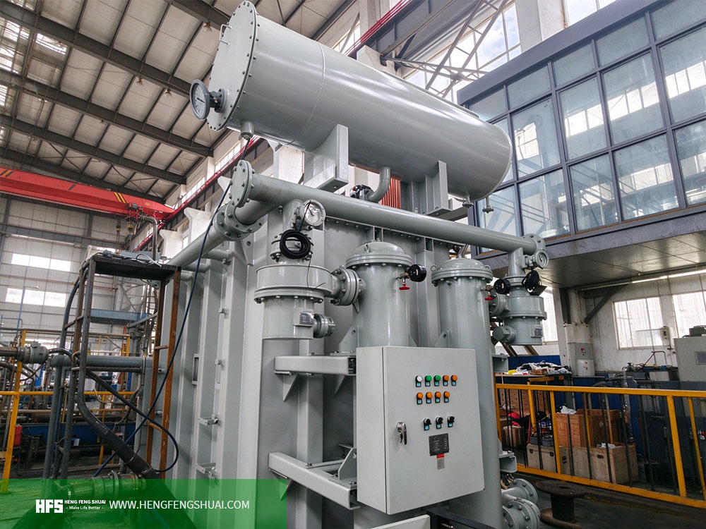
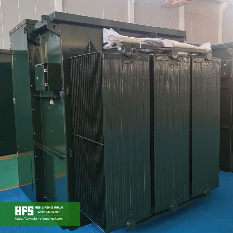
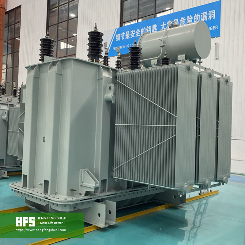
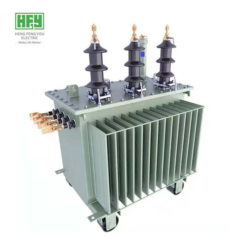
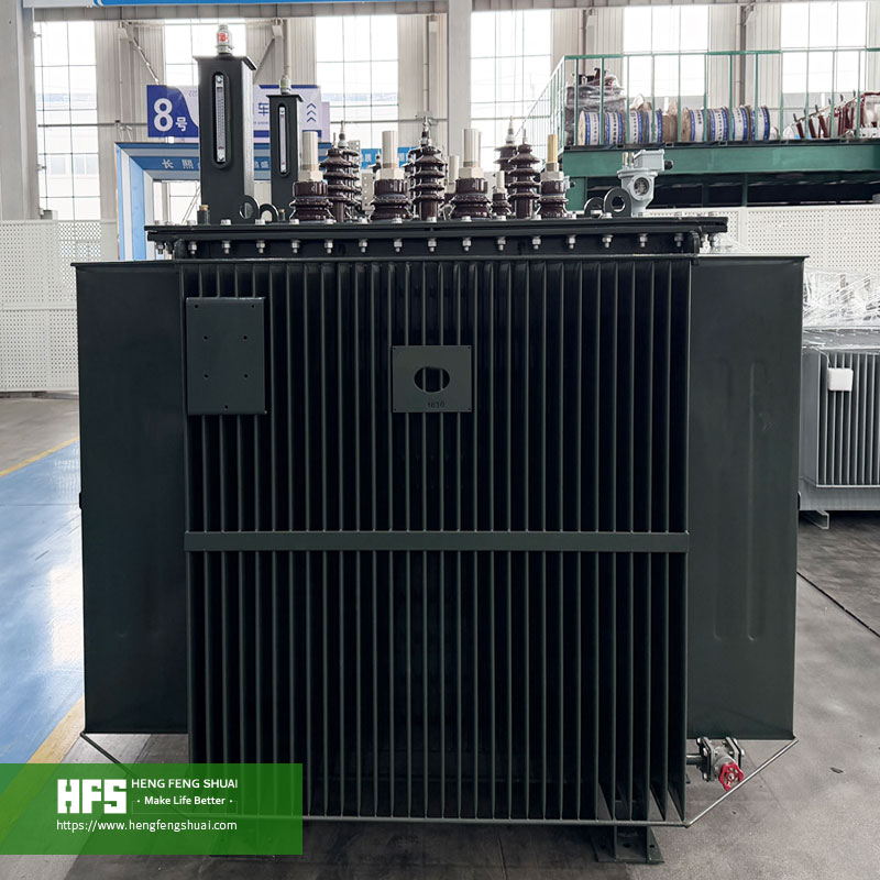
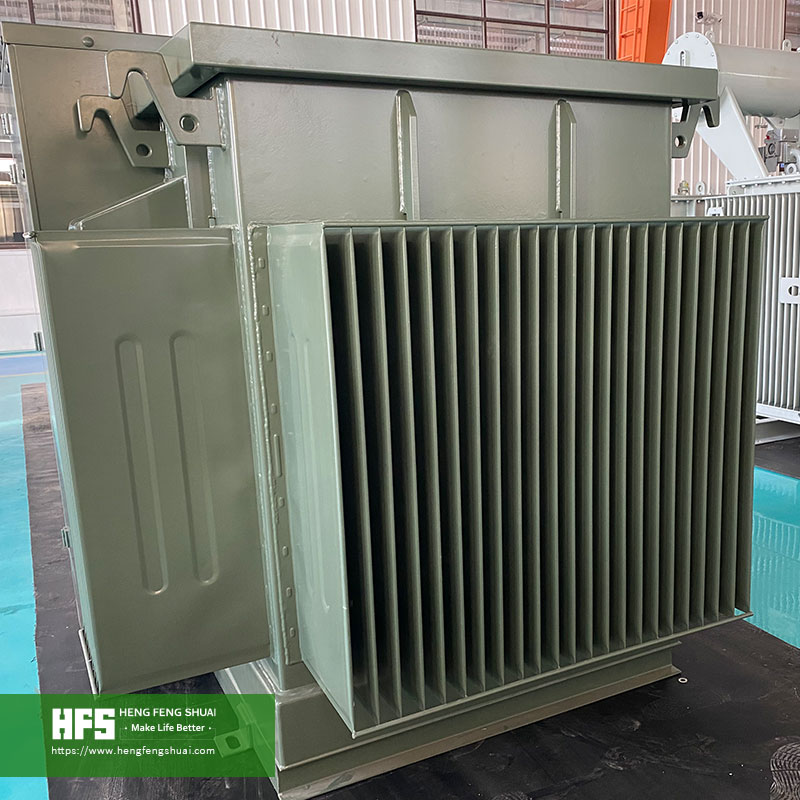
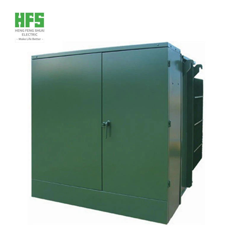
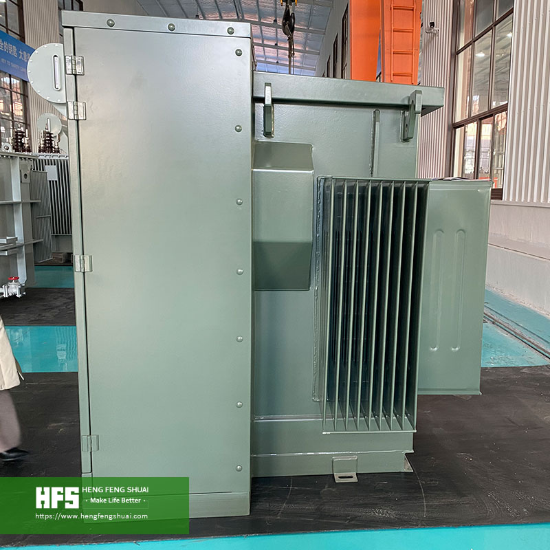
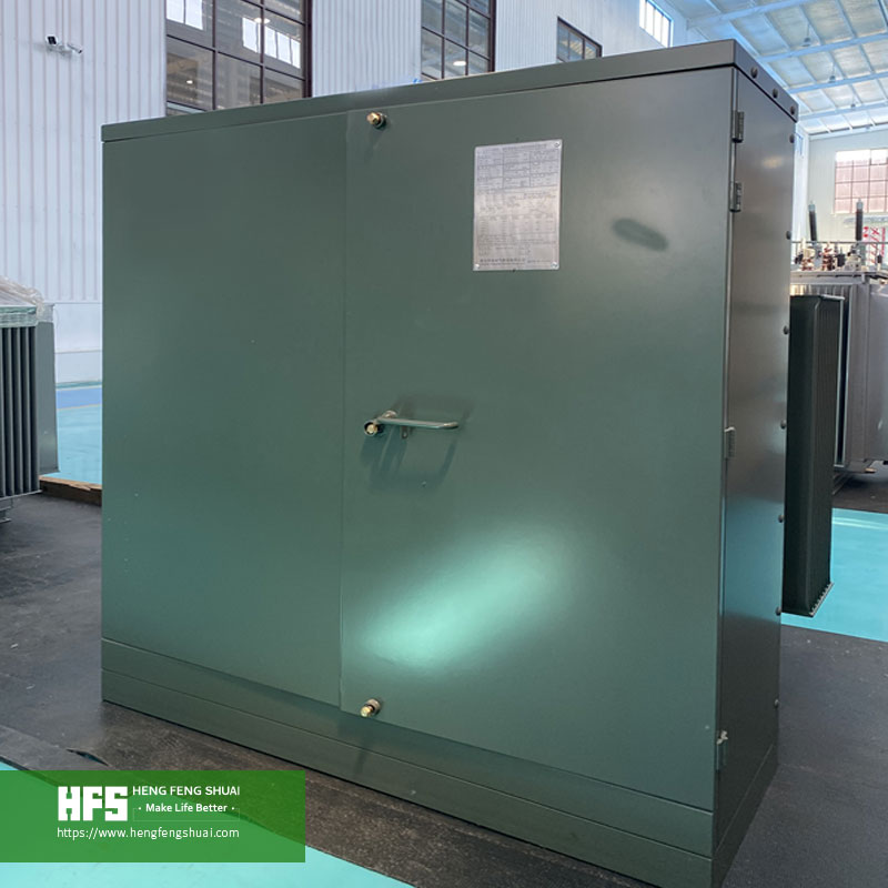
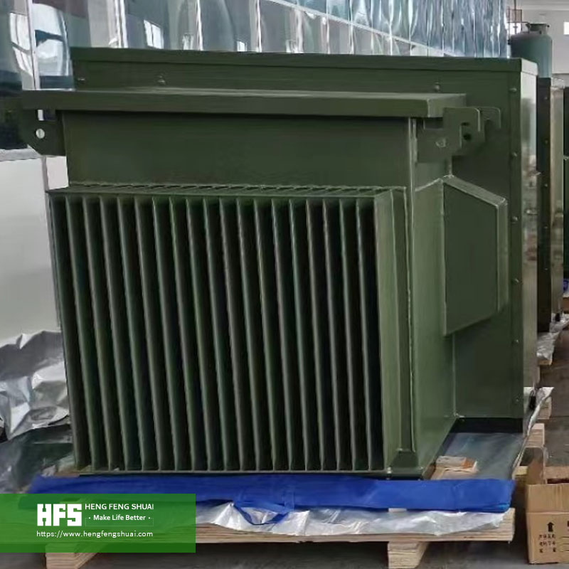
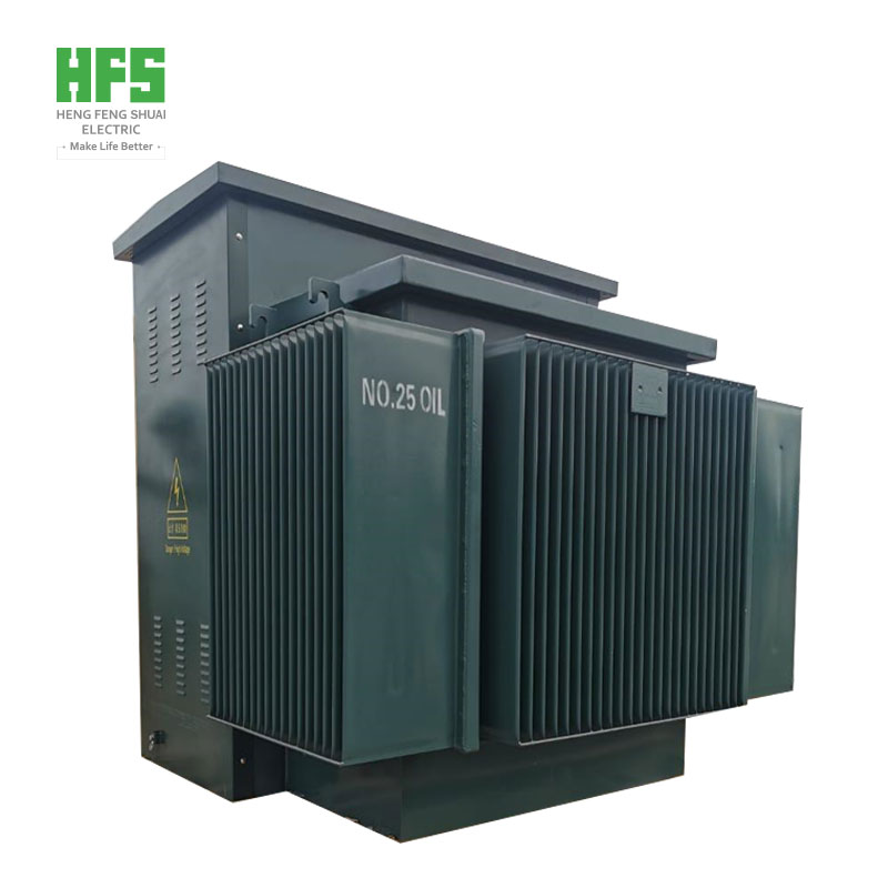
60 Hz Power Grid · 33 kV / 13.8 kV Power Distribution · 50‑130 MVA On‑load Tap‑changing Electric‑arc Furnace Transformer System
Ⅰ. Application Requirements for Power Supply and Distribution System of Arc Furnace in Saudi Steel Plant
1. Load Characteristics of Electric‑arc Furnace Short‑process Steelmaking
Benefiting from natural gas resources, Saudi Arabia’s steel industry adopts the short‑process production route combining gas‑based direct reduced iron (DRI) and electric‑arc furnace. Major steel enterprises are located in industrial zones including Jubail, Rabigh and Ras Al‑Khair. Power consumption for smelting and refining accounts for over 60% of total plant power consumption. Therefore, electric‑arc furnace transformer acts as core equipment determining production output, specific power consumption per ton of steel and equipment availability.
One complete smelting cycle of an electric‑arc furnace follows the sequence of arc striking, melting, melt‑down, temperature rising and tapping. During melting stage, dramatic variation of arc length and periodic short‑circuit caused by furnace burden collapse bring repeated impact with secondary‑side current at the level of tens of kilo‑amperes. Taking a 100 t ultra‑high‑power furnace as an example, with 20‑24 heats per day and specific power consumption of 350‑450 kWh per ton of steel, the transformer is subjected to dozens of switching‑on/off and short‑circuit impacts every day. Its operating intensity is far higher than conventional distribution transformers.
From power‑supply perspective, electric‑arc furnace represents a typical impact‑type load: power surges upon energization and drops sharply upon arc interruption or furnace shutdown, accompanied by large fluctuation of reactive power demand. Accordingly, the transformer shall feature sufficient short‑time overload capacity and fast tap‑changing response. Matching switchgears shall also adapt to frequent‑operation working conditions.
2. Adaptation Requirements for Saudi Power Grid and Site Conditions
Saudi Electricity Company (SEC) adopts 33 kV and 13.8 kV for medium‑voltage distribution, with 380 V or 400 V for low‑voltage side, and rated frequency of 60 Hz. Direct adoption of domestic Chinese 50 Hz, 110/35/10 kV solutions is not feasible. Key differences are shown in Table 1.
Table 1 Typical Parameter Comparison between Chinese and Saudi Steel‑project Power Grids
| Item |
Typical Chinese Configuration |
Typical Saudi Configuration |
| Grid frequency |
50 Hz |
60 Hz |
| High‑voltage incoming |
110 kV / 35 kV |
132 kV / 33 kV |
| Medium‑voltage distribution |
35 kV / 10 kV |
33 kV / 13.8 kV |
| Low‑voltage distribution |
400 V |
380 V or 400 V |
| Extreme summer ambient temperature |
Around 40 ℃ |
Up to 50 ℃; inland areas exceed 52 ℃ |
| Ambient characteristics |
Ordinary industrial dust |
Sand‑dust storm; coastal salt mist |
| Applicable transformer standards |
GB 1094 series |
IEC 60076 series, SEC specifications, SASO certification |
Frequency variation will change core magnetic flux density, percentage impedance and operating point of cooling fans. Direct reuse of 50 Hz design will result in impedance deviation and insufficient temperature‑rise margin. All equipment in this project is recalculated for 60 Hz with corresponding type‑test reports provided.
3. Three Hierarchies of Power Supply and Distribution System
For the main furnace circuit, power comes from 33 kV or 13.8 kV incoming supply, steps down via furnace transformer to 200‑450 V, and is fed into furnace bath through short‑net and graphite electrodes. It features maximum capacity and harshest operating conditions. Refining and auxiliary systems consist of LF transformer, dust‑removal fans, cooling‑water circulation and continuous‑casting drives. Although loads are relatively stable, power failure will cause downgrade of entire molten steel batch. Plant‑wide power distribution is undertaken by 13.8 kV/0.4 kV and 33 kV/0.4 kV distribution transformers plus low‑voltage switchgears for control & instrumentation, lighting and maintenance.
Ⅱ. Main Challenges for Type‑selection of Furnace Transformers for Saudi Steel Plants
Dynamic load and short‑circuit impact. Furnace transformer capacity is generally configured at 600‑800 kVA per ton of furnace capacity; upper limit is adopted for ultra‑high‑power furnaces. Insufficient capacity will prolong melting duration and raise power consumption. Too‑low impedance will lead to excessive short‑circuit current and aggravate thermal load on electrodes and short‑net. Per IEC 60076‑5, reactance variation after short‑circuit test shall be controlled within 2%.
Low‑voltage high‑current secondary‑side design. Secondary‑side voltage ranges 200‑450 V with current reaching 10‑60 kA. Additional loss and local overheating tend to occur on short‑net and outlet terminals. Specialized design shall be implemented for large‑cross‑section copper busbars, bushing clearance, electromagnetic shielding and short‑net impedance so as to avoid excessive terminal temperature rise and accelerated insulation ageing.
Difference of 60 Hz and local voltage sequence. Saudi projects generally require compliance with IEC 60076 together with SASO certification and SABER registration. Tender documents normally demand 60 Hz type‑test data as well as measured loss and impedance values. 50 Hz test reports from China cannot substitute for these.
High temperature, sand‑dust and salt‑mist environment. Extreme summer temperature exceeds 50 ℃. Sand‑dust accumulation on radiators degrades heat dissipation efficiency; coastal industrial zones suffer salt‑mist corrosion. Equipment designed for standard 40 ℃ ambient condition usually requires 5%‑10% derating under such site conditions.
Power‑quality and grid‑connection requirements. Electric‑arc furnace causes voltage fluctuation, flicker and harmonics of 2nd,3rd,4th,5th,7th orders. SVC or filter devices shall be equipped and calculated in coordination with transformer impedance and protection setting values. Per Saudi grid requirements at point of common coupling, flicker and total harmonic distortion shall be verified by on‑site measurement prior to grid‑connection.
Replacement of aged equipment. Furnace transformers in service for more than 20 years commonly suffer missing nameplates, insulation ageing and increased losses. For replacement projects, installation dimensions, oil sump and short‑net interfaces must be checked; otherwise rework risk of site mis‑fit exists.
Ⅲ. HENGFENGSHUAI Furnace Transformer and Power‑distribution System Solution
1. System Architecture and Core Equipment
HENGFENGSHUAI adopts three‑tier architecture of “smelting main circuit — refining & auxiliary systems — plant‑wide power distribution” for complete‑set equipment with unified electrical interfaces and protection coordination. Power flow: 33 kV or 13.8 kV incoming → medium‑voltage switchgear → furnace transformer (with series reactor) → short‑net → graphite electrode → molten bath. Meanwhile, power is supplied to ladle furnace via LF transformer, and stepped‑down to 380/400 V for auxiliary systems by distribution transformers.
Functions of core equipment: Furnace transformer performs voltage transformation and on‑load tap‑changing to track power demand in each smelting stage. Series reactor limits short‑circuit current and stabilizes electric‑arc combustion. LF transformer is sized at 20%‑40% of furnace transformer capacity, featuring large tap quantity and small step‑voltage difference for precise temperature control in refining process. Medium‑voltage switchgear implements switching‑on/off, protection, metering and measurement & control. Distribution transformers and low‑voltage cabinets supply power for dust‑removal, water pumps and continuous‑casting drives, with reserved soft‑starter or variable‑frequency drive interfaces for large‑capacity motors.
2. Eight‑item Parameter Verification for Furnace Transformer Type‑selection
HENGFENGSHUAI verifies the following parameters item‑by‑item according to customer specifications, furnace data and power‑system conditions to guarantee matching between equipment and process conditions.
* Rated capacity: Preliminary selection at 600‑800 kVA per ton furnace capacity, further verified against smelting cycle and overload capability. 80‑100 MVA is commonly specified for 100 t ultra‑high‑power furnaces.
* Primary‑side voltage: 33 kV or 13.8 kV per SEC incoming specification; 132 kV direct incoming is available for large integrated steel mills.
* Secondary‑side voltage & current: Max. 400‑450 V, min. 200‑250 V; rated current converted from capacity, typically 10‑60 kA.
* Tap‑changing mode & tap quantity: On‑load tap‑changing, typically 17‑23 taps with step voltage 8‑20 V.
* Impedance voltage: 6%‑12% including series reactor, defined by furnace type and system short‑circuit capacity.
* Cooling mode: ONAN / ONAF / OFAF combination determined by ambient temperature and load profile; 10%‑15% heat‑dissipation margin reserved for 50 ℃ ambient.
* Insulation & temperature rise: LI/AC level defined per IEC 60076‑3; winding temperature rise ≤65 K, top‑oil temperature rise ≤60 K.
* Operating condition & acceptance: Clarify annual operating hours, load curve, installation method, applicable standards and test item list.
One‑time parameter confirmation before procurement significantly reduces risks of design change, manufacturing deviation and delivery delay.
3. Configuration for High‑temperature, Sand‑dust and Salt‑mist Environment
Temperature‑rise calculation is performed at 50 ℃ ambient condition. Radiator area is increased by 10%‑15% versus standard design. Cooling fans can be switched in groups to reduce auxiliary power consumption under light‑load conditions. Fully‑sealed tank is equipped with gas‑bag conservator and maintenance‑free breather. External accessories are fitted with dust covers; radiator fin spacing is enlarged for convenient flushing. C4 anti‑corrosion grade with minimum dry‑film thickness 150 μm is applied for inland sites. Coastal sites adopt C5‑M heavy‑duty anti‑corrosion coating with minimum dry‑film thickness 250 μm, passing 720‑hour neutral salt‑spray test. Protection grade for outdoor enclosures is no less than IP54.
4. Switchgear, Auxiliary Power Distribution and Replacement Service
Medium‑voltage switchgears are rated at 36 kV and 17.5 kV, rated current 630‑1250 A, short‑circuit breaking capacity 25‑31.5 kA, complying with IEC 62271‑200 internal‑arc classification IAC AFLR. Vacuum circuit‑breakers with mechanical endurance ≥10 000 operations are adopted. Distribution transformers are supplied at 33/0.4 kV and 13.8/0.4 kV, capacity 500‑2500 kVA, Dyn11 vector group, losses controlled per IEC 60076‑20 and SASO energy‑efficiency requirements. Low‑voltage cabinets are designed according to IEC 61439 with main busbar rated up to 4000 A and short‑time withstand 65 kA / 1 s.
For replacement projects, on‑site survey and interface check are carried out: re‑verify original nameplate data, foundation dimension, oil‑sump volume, cable‑in/out orientation and short‑net interfaces. 3D scanning is deployed if necessary to reconstruct installation space. Where drawings are missing, electrical parameters are deduced from field measurement. Shutdown window and commissioning responsibility boundary are clearly specified in technical agreement.
5. Technical Documentation and Quality Support
Technical datasheets, product drawings, calculation documents and factory acceptance test reports are delivered together with equipment. For projects with special inspection requirements, applicable standards, test items, witnessing modes and document list can be defined in technical agreement. We support SASO certification, SABER registration and third‑party on‑site acceptance. Confirming parameters and document scope in procurement phase cuts communication cost in manufacturing, acceptance and operation‑maintenance. Random technical documents are provided in both Chinese and English for EPC contractor and owner filing.
Ⅳ. Recommended Products and Key Technical Parameters
1. Electric‑arc Furnace Transformer
HSSPZ‑series on‑load tap‑changing construction, customizable according to furnace capacity, secondary‑side voltage and process requirements. Typical parameters are listed in Table 2.
Table 2 Typical Technical Parameters of Electric‑arc Furnace Transformer
| Parameter Item |
Typical Range / Index |
| Rated capacity |
50 / 60 / 80 / 100 / 120 / 130 MVA (customizable) |
| Primary‑side rated voltage |
33 kV / 13.8 kV / 132 kV |
| Secondary‑side rated voltage |
200‑450 V, on‑load tap‑changing 17‑23 taps |
| Secondary‑side rated current |
10‑60 kA |
| Impedance voltage |
6%‑12% (including reactor) |
| Vector group |
Yd11 |
| Cooling mode |
ONAN / ONAF / OFAF |
| Rated frequency |
60 Hz (50 Hz version available) |
| Temperature‑rise limit |
Winding ≤65 K; top‑oil ≤60 K |
| Partial discharge |
≤10 pC (at 1.5 Um) |
| Noise level |
≤75 dB(A), measured at 1 m distance |
| Design service life |
≥30 years |
| Anti‑corrosion grade |
C4 / C5‑M |
| Applicable standards |
IEC 60076, IEC 60214‑1, SASO certification |
Table 3 Typical Technical Parameters of Ladle Furnace Transformer
| Parameter Item |
Typical Range / Index |
| Rated capacity |
10 / 16 / 20 / 25 / 32 / 40 MVA |
| Voltage combination |
33 kV or 13.8 kV / 250‑420 V |
| Tap‑changing mode |
On‑load tap‑changing, small voltage step, large tap quantity |
| Impedance voltage |
6%‑8% |
| Vector group / Cooling |
Yd11; ONAN / ONAF |
| Frequency / Temperature rise |
60 Hz; winding ≤65 K, top‑oil ≤60 K |
| Design service life |
≥30 years |
3. Medium‑voltage Switchgear and Distribution Transformer
Table 4 Typical Technical Parameters of Medium‑voltage Switchgear (33 kV / 13.8 kV)
| Parameter Item |
Typical Range / Index |
| Rated voltage |
36 kV / 17.5 kV |
| Rated current |
630‑1250 A |
| Short‑circuit breaking / Short‑time withstand |
25‑31.5 kA; 25 kA / 3 s |
| Internal‑arc classification |
IAC AFLR (IEC 62271‑200) |
| Circuit‑breaker |
Vacuum circuit‑breaker, mechanical endurance ≥10 000 operations |
| Protection / Frequency |
IP4X (cabinet), IP54 (outdoor); 60 Hz |
| Applicable standards |
IEC 62271‑200, IEC 62271‑100 |
More about Medium‑voltage Switchgear
Table 5 Typical Technical Parameters of Distribution Transformer (33/0.4 kV, 13.8/0.4 kV)
| Parameter Item |
Typical Range / Index |
| Rated capacity |
500 / 800 / 1250 / 1600 / 2000 / 2500 kVA |
| Vector group / Impedance |
Dyn11; 6% |
| Cooling / Protection |
ONAN; IP54 (outdoor) |
| Loss level |
Controlled by IEC 60076‑20 and SASO energy‑efficiency requirements |
| Anti‑corrosion / Service life |
C4 / C5‑M; ≥25 years |
* Specialized electromagnetic design for 60 Hz. Core flux density is controlled no higher than 1.60 T at rated voltage. Impedance and loss are recalculated for 60 Hz to avoid impedance deviation and insufficient temperature‑rise margin caused by adopting 50 Hz design. 60 Hz measured test data are supplied from factory acceptance test.
* Short‑circuit withstand and thermal stability. Windings adopt high‑purity oxygen‑free copper with conductivity ≥99.9% IACS; transposed conductors are applied to reduce circulating‑current loss. Short‑circuit verification is performed per IEC 60076‑5 to sustain dozens of daily short‑circuit impacts; reactance change after short‑circuit test is limited within 2%.
* Cooling redundancy for high‑temperature conditions. Temperature‑rise verified at 50 ℃ ambient; 10%‑15% heat‑dissipation margin reserved. Third‑stage OFAF cooling enables continuous operation at 1.2 times rated load for 2 hours.
* Low loss and high economy. Efficiency of large‑capacity unit at rated condition ≥98.5%. Taking a 100 MVA transformer as example: 0.1‑percentage‑point loss reduction with 7000 operating‑hours per year can save around 700 000 kWh energy loss annually.
* Anti‑corrosion and compliance delivery. C5‑M coating system passes 720‑hour neutral salt‑spray test. Fully‑sealed oil tank reduces maintenance frequency. Test reports covering ratio, impedance, loss, temperature‑rise, insulation, lightning impulse and partial discharge are provided complying with IEC 60076. Support SASO certification, SABER registration and third‑party witnessing.
* One‑stop complete‑set supply and interface coordination. Furnace transformers, LF transformers, medium‑voltage switchgears and distribution transformers are supplied by single vendor with unified design for voltage class, protection setting and interface dimension. It minimizes multi‑party EPC coordination and on‑site rework risk.
Ⅵ. Application Scenarios and Capacity Matching
This solution applies to new‑build electric‑arc furnace workshop main circuit and auxiliary power distribution, power supply for ladle refining furnace and vacuum degassing unit, power distribution for continuous‑casting and rolling line, power distribution for dust‑removal & cooling‑water system, as well as overall replacement of furnace transformers and switchgears with service life exceeding 20 years. For phased‑construction steel mills, main transformers can be commissioned unit‑by‑unit with reserved interface for parallel operation and future capacity expansion.
Table 6 Typical Capacity Matching between Electric‑arc Furnace and Transformer
| Nominal capacity of EAF |
Rated capacity of transformer |
Max. secondary‑side voltage |
Reference secondary‑side rated current |
| 70 t |
50‑60 MVA |
350‑400 V |
approx. 80‑100 kA |
| 80 t |
60‑70 MVA |
380‑420 V |
approx. 90‑105 kA |
| 100 t |
80‑100 MVA |
400‑450 V |
approx. 110‑145 kA |
| 130 t |
100‑130 MVA |
420‑460 V |
approx. 135‑180 kA |
| 150 t |
120‑150 MVA |
430‑480 V |
approx. 160‑200 kA |
Note: Secondary‑side current is calculated from rated capacity at maximum secondary‑side voltage. Actual value is affected by tap quantity and short‑net voltage drop. LF transformer shall be sized at 20%‑40% of above‑listed transformer capacity. Final capacity shall be verified according to furnace type, smelting cycle and owner specifications.
Ⅶ. Typical Configuration Reference
1. New‑build 100 t Ultra‑high‑power EAF + LF Workshop
Main circuit is equipped with one set of 100 MVA, 33 kV / 400‑450 V on‑load tap‑changing furnace transformer together with series reactor and 33 kV incoming cabinet. Refining zone adopts one 32 MVA LF transformer. Auxiliary zone installs two sets of 2000 kVA, 33/0.4 kV distribution transformers and low‑voltage cabinets for dust‑removal fans, cooling‑water circulation and continuous‑casting drives. Complete‑set equipment is supplied for 60 Hz, 50 ℃ ambient condition with C4 / C5‑M anti‑corrosion grade. Separate metering is configured for main smelting circuit and auxiliary circuit to avoid voltage disturbance from smelting impact load upon auxiliary systems.
2. Overall Replacement of 70 t EAF Transformer
Adopt workflow of “site survey → design → manufacturing”. Re‑measure foundation dimension, oil sump, cable‑in/out orientation and short‑net interfaces. New transformer capacity is upgraded to 55‑60 MVA with ONAN/ONAF cooling and on‑load tap‑changing. Overall outer dimension matches original unit to guarantee replacement and commissioning within planned furnace‑shutdown window.
3. Complete Auxiliary‑system Power‑distribution Package
Configure 4‑6 units of 13.8 kV/0.4 kV distribution transformers with single‑unit capacity 800‑2500 kVA according to load list, matched with low‑voltage cabinets and motor‑control circuits. Reserve soft‑start and variable‑frequency‑drive interfaces for large‑capacity motors such as dust‑removal fans and water pumps. Zonal metering is implemented for each process area to support zonal energy‑consumption assessment.
Ⅷ. Frequently‑asked Questions
Q1: How to determine the capacity of furnace transformer?
A: Make preliminary selection at 600‑800 kVA per‑ton furnace capacity, then verify against smelting cycle, specific power consumption and overload capacity. 80‑100 MVA is commonly used for 100 t ultra‑high‑power furnace. If continuous charging and foaming‑slag operation are adopted and smelting cycle is shortened within 45 minutes, upper‑limit capacity with additional 10% margin is recommended.
Q2: What are major differences versus ordinary distribution transformer?
A: Furnace transformer is designed for low‑voltage high‑current application and periodic short‑circuit shock, secondary‑side voltage 200‑450 V with current up to 10‑60 kA, equipped with multi‑step on‑load tap‑changer and dedicated impedance. Conventional distribution transformer focuses on voltage transformation and long‑term stable operation with typical impedance of 4%‑6%.
Q3: Why must Saudi‑project transformers be designed for 60 Hz?
A: Frequency change will alter core magnetic flux, impedance percentage and fan operating point. If a 50 Hz transformer is operated on 60 Hz grid, impedance deviation may reach 15%‑20%, disturbing short‑circuit‑current distribution and protection coordination. Cooling air flow will also deviate from design value. Recalculation and 60 Hz type‑test reports are mandatory.
Q4: Is derating required under high‑temperature environment?
A: Units specially designed for 50 ℃ ambient, equipped with third‑stage OFAF cooling and 10%‑15% heat‑dissipation margin can run continuously at rated capacity. Equipment designed for standard 40 ℃ normally requires 5%‑10% derating. Temperature reference and derating curve shall be clearly specified in technical agreement.
Q5: What documents are required for replacement projects?
A: Original nameplate data, drawings and installation dimensions, foundation & oil‑sump conditions, short‑net interface form, operation records and furnace‑shutdown window. If documentation is incomplete, supplier can perform site survey to deduce parameters. Responsibility boundary for interface confirmation shall be defined in contract.
Q6: What parameters shall be provided for furnace‑transformer procurement?
A: Rated capacity, primary‑side & secondary‑side voltage, secondary‑side current, tap‑changing range & tap quantity, impedance, cooling mode, rated frequency, ambient temperature, installation method, anti‑corrosion grade, applicable standards and acceptance‑test list. For replacement projects, original‑unit parameters and interface information shall also be provided for one‑time type‑selection verification.
Ⅸ. Contact HENGFENGSHUAI Electric
If you are planning new‑build Saudi steel plant, EAF‑line expansion or retrofit & replacement of existing furnace transformers, please provide voltage sequence, furnace type & capacity, secondary‑side voltage‑current, ambient temperature, site condition and applicable standards. HENGFENGSHUAI can deliver type‑selection suggestion and complete‑set configuration proposal for furnace transformers, LF transformers, medium‑voltage switchgears and distribution transformers.
E‑mail: hfs@hengfengshuai.com
Request the Solution