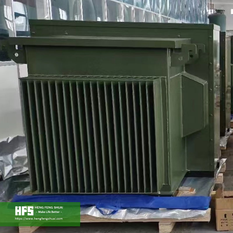
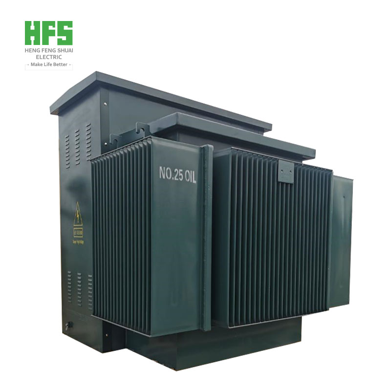
Most incoming inquiry emails only include two figures: one capacity value and one voltage ratio. While quotations can be generated based solely on these two parameters, they are insufficient for finalizing a transformer specification. Gaps in requirements are usually uncovered at the design‑review stage, by which time switchgear ratings have already been fixed and transportation route surveys completed.
Decisions made at this stage will define equipment performance for 25‑30 years: short‑circuit breaking capacity for switchgears, actual voltage at feeder terminals, no‑load losses that incur power costs for all 8760 hours per year, and transportation weight that determines whether the unit can be delivered to site. This article walks through the practical decision‑making sequence and highlights the most frequent pitfalls.
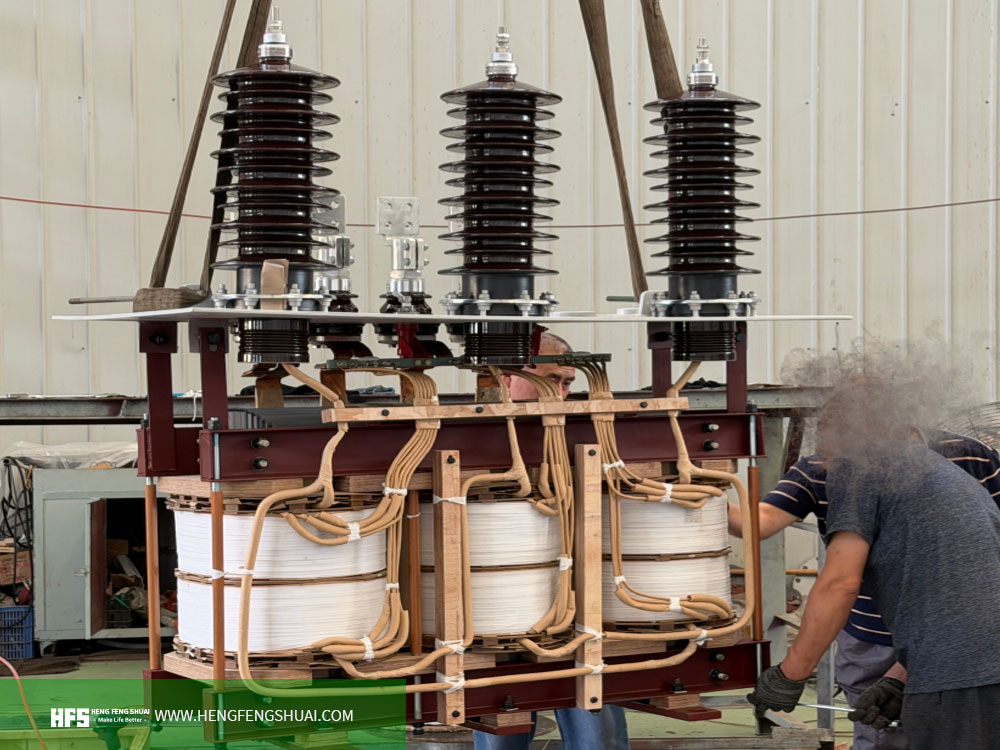
I. Define Load First, Then Determine Capacity
Capacity is an output of the selection process, not an input. The starting point is load data.
Calculate from installed load in kW and apply three corrections: demand factor, diversity factor and power factor. Transformers are rated in kVA. For an 800 kW load at 0.85 power factor, the corresponding value is 941 kVA before adding any margin.
Two parameters drive subsequent design work: peak load and load profile. When large motors start directly, inrush current can reach 6‑8 times rated current; the transformer itself can withstand this, yet voltage drop at terminals becomes the real concern. On‑site practice generally limits voltage dip to 10%‑15%. Compliance with this threshold depends on transformer short‑circuit impedance, meaning capacity and impedance cannot be specified independently.
Load profile governs thermal design. Operating steadily at 70 % loading for 20 hours per day is a completely different operating condition compared with spiking to 110 % for 45 minutes. Differences manifest in winding temperature,
insulation‑aging rate and expected service life — none of which appear on the nameplate. Short‑term overload capability is defined in IEC 60076‑7 for calculation purposes, yet it depends on pre‑overload loading factor and ambient temperature and must be computed for the specific unit. Applying generic percentage values is not valid.
Finally, consider design margin. A 20%‑25 % uplift above calculated load is common practice. Excessive margin means paying ongoing no‑load‑loss charges for capacity rarely utilised. This margin should be clearly stated in inquiry documents; otherwise vendors will apply their own convenient assumptions.
II. Confirm Primary and Secondary Voltages
Specify both nominal system voltage and actual operating voltage for each winding, as these two values often diverge. A 11 kV grid may operate at 10.5 kV in reality. A transformer designed for exactly 11 kV will permanently operate at an off‑nominal tap position.
Tap range and tap‑changer type must be explicitly defined and must not be left blank. Distribution transformers conventionally adopt ±2×2.5 % off‑circuit tap‑changers to accommodate ±5 % system‑voltage fluctuation. If operational voltage drift is expected or voltage regulation for the network is required, an on‑load tap‑changer is necessary. This represents a different unit with distinct cost, maintenance and protection requirements.
Insulation level is a parameter independent of rated voltage and is frequently omitted from specifications. Windings must withstand lightning impulse and power‑frequency withstand voltages of the connected system. For a 33 kV winding, typical values are 170 kV lightning impulse withstand and 70 kV power‑frequency withstand. These values are critical for transformers connected directly to overhead lines or installed in high‑lightning‑risk areas. For indoor installations fed by cables, the same values may be over‑specified. Follow utility requirements instead of copying generic tables.
Vector group forms part of the same decision. It defines phase‑angle relationships between primary and secondary windings, establishes paths for unbalanced loads and zero‑sequence harmonics, and constitutes a hard constraint for future parallel‑operation with existing equipment. For distribution transformers feeding four‑wire low‑voltage networks, Dyn11 is standard. Two transformers with differing vector groups cannot operate in parallel regardless of other matching parameters.
III. Frequency Is More Than a Nameplate Label
Changing frequency for an identical winding assembly requires re‑designing the magnetic circuit, so frequency is a fundamental design input. A core designed for 50 Hz operated at 60 Hz achieves lower magnetic flux density, reduced no‑load losses and improved temperature‑rise margin. The reverse scenario is problematic: energising a 60 Hz core at 50 Hz leads to magnetic saturation.
Core‑steel grades deserve separate specification for 60 Hz projects. High‑grain‑oriented silicon steel (Hi‑B grades) is standard. Ordinary grades may appear to meet loss targets on paper, yet offer almost no allowance for manufacturing scatter. Loss baselines differ between the two frequencies; comparing 50 Hz loss figures against a 60 Hz project yields invalid comparisons.
If future‑site‑frequency conversion is possible, state this in the inquiry. Dual‑frequency capability must be designed‑in from the start and cannot be retrofitted.
IV. Evaluate Load Characteristics, Not Merely Total Load
Two projects with identical demand may require different transformers, driven by load nature.
- Impact loads (electric‑arc furnaces, rolling mills, welding equipment): subject windings and tap‑changers to repeated thermal cycling. Thermal‑cycle stress verification is required rather than only steady‑state temperature‑rise checks. Increased impedance is often specified to limit current fluctuations.
- Non‑linear loads: inject harmonic currents that raise winding eddy‑current losses, potentially causing local overheating even when rms current readings appear acceptable. Rectifiers, variable‑frequency drives, data‑centre IT loads and photovoltaic inverters fall within this category. For high‑harmonic environments, provide harmonic‑spectrum data so windings can be purpose‑designed.
- Frequently started large motors: produce voltage dips and impose upper limits on impedance values.
- Three‑phase transformers supplying single‑phase loads: risk three‑phase unbalance and require delta‑connected windings to provide zero‑sequence paths.
Special consideration applies to photovoltaic and wind‑power applications. Their loads are inverters rather than motors, characterised by defined harmonic spectra and different reactive‑power‑absorption behaviour, with operating profiles determined by renewable‑resource availability. Selection is governed by inverter‑output voltage, collection‑system design and grid‑connection codes. Applying motor‑load models to photovoltaic projects is a common cause of incorrect‑impedance specification.
V. Specify Impedance Before Finalising Switchgear
Short‑circuit‑impedance percentage links transformer, switchgear and protection settings, yet it is often copied from legacy specifications without re‑evaluation.
Its primary function is limiting short‑circuit current. Neglecting system‑side impedance, the approximate three‑phase short‑circuit current on the low‑voltage side for a transformer of rated power S (MVA) and voltage U (kV) is:
Isc ≈ S / (√3 × U × uk)
The approximation itself is less important than its sensitivity. Example for a 20 MVA, 11 kV transformer:
| Rated Power |
Voltage |
Short‑circuit Impedance uk |
Estimated Low‑voltage Short‑circuit Current |
| 20 MVA |
11 kV |
6 % |
17.5 kA |
| 20 MVA |
11 kV |
8 % |
13.1 kA |
| 20 MVA |
11 kV |
10 % |
10.5 kA |
A two‑percentage‑point change in impedance reduces short‑circuit current from 17.5 kA to 13.1 kA. Where switchgear is rated for 16 kA, this directly determines adequate equipment rating. This explains why impedance values cannot be reused across different projects: switchgear ratings change, but impedance specifications are not updated accordingly.
Higher impedance comes with the penalty of increased voltage regulation. Units with uk = 10 % exhibit larger on‑load voltage drop compared with uk = 6 % designs; this drop compounds with cable voltage drop over long feeders. Typical distribution‑transformer impedance ranges from 4 %‑6 %, while large power transformers commonly reach 10 %‑14 %.
Mandatory conditions for parallel‑operation of two or more transformers: identical vector group, equal transformation ratio, corresponding tap positions, and impedance deviation within approximately 10 %. Violation of any condition results in circulating current even under no‑load conditions.
Impedance carries manufacturing tolerances. IEC 60076‑1 permits measured values to deviate ±10 % from declared values unless tighter guarantees are contractually agreed. Design‑phase risk arises when switchgear ratings leave no tolerance for this deviation.
VI. Cooling Modes and Defining Which Rated Capacity Applies
Cooling‑mode designations follow IEC 60076‑2: internal medium first, followed by external medium, with additional letters for forced circulation. ONAN denotes oil natural, air natural; ONAF adds cooling fans; OFAF incorporates forced‑oil circulation.
Practically speaking, cooling mode alters the achievable rated capacity for an identical active part. A 10 MVA ONAN unit with unchanged core and windings may be marked 12.5 MVA ONAF. Trade‑offs include fans, fan‑failure operating modes, auxiliary‑station‑power consumption and noise. Apparent commercial advantage in quotations may lead to operational difficulty: when fans stop, capacity reverts to the ONAN rating, requiring either load shedding or risking winding overheating.
Therefore specifications must clarify whether the purchased rating corresponds to fans‑on or fans‑off conditions. Where short‑term peak loads exceed the principal rated capacity, define requirements for forced‑oil‑circulation ratings and permissible duration. Noise assessment belongs within this scope: ONAN sound‑power levels cannot represent ONAF performance. For installations near site boundaries or residential zones, noise constitutes a planning constraint rather than merely a comfort consideration.
VII. Compare Loss‑Capitalised Total Cost, Not Only Purchase Price
Two transformers complying with specification limits may differ in full‑life‑cycle cost by tens of thousands of US dollars, as procurement price excludes lifetime energy losses.
The standard methodology applies loss capitalisation. Assign monetary values per watt for no‑load loss (coefficient A) and load loss (coefficient B), derived from electricity tariff, load factor and buyer‑specified discount rate.
Total Evaluated Cost = Purchase Price + A × P₀ + B × Pₖ
Example comparison for two compliant 2000 kVA, 50 Hz distribution‑transformer proposals:
| |
Proposal A |
Proposal B |
| Purchase Price (USD) |
42,000 |
49,000 |
| No‑load Loss P₀ (W) |
2,100 |
1,500 |
| Load Loss Pₖ (W) |
18,000 |
15,000 |
| Evaluated Cost (A = 6.0 / B = 1.5) |
81,600 |
80,500 |
| Evaluated Cost (A = 3.0 / B = 0.75) |
61,800 |
64,750 |
Under the first set of coefficients, Proposal B carries a $7000 higher purchase price yet delivers net economic benefit of $1100. With the second coefficient set, Proposal A yields a $2950 advantage. Identical hardware can produce opposite outcomes depending on coefficient selection. Since A and B are buyer‑specific values, either provide these coefficients within inquiry documents or explicitly state evaluation criteria. Otherwise raw purchase‑price comparison becomes misleading.
Additionally, loss values stated in specifications represent maximum permissible limits, not guaranteed measured values. IEC 60076‑1 allows +15 % tolerance for no‑load loss, +15 % for load loss and +10 % for total loss. Units delivered at these upper tolerance limits still meet formal compliance. Explicitly request guaranteed loss values if required, accepting corresponding reduction in design margin.
VIII. Consider Installation‑Site Conditions
Transformer ratings are defined for reference ambient conditions: maximum 40 °C, daily‑average 30 °C, annual‑average 20 °C. Sites exceeding these criteria — including regions across the Gulf, large portions of Africa and northern Australia — require rating derating. Adding fans alone does not constitute proper derating; temperature‑rise limits must be assessed against actual site ambient temperature.
Altitude similarly affects performance. Above 1000 m, reduced air density impairs external insulation and heat dissipation, requiring recalculation of withstand‑voltage and temperature‑rise limits. For altitudes exceeding 2000 m, altitude correction is a primary design input rather than a footnote.
External creepage distance for outdoor bushings shall match site pollution severity, normally expressed as specific creepage distance in mm/kV relative to maximum system voltage. Coastal locations, cement‑plant surroundings and desert regions with high sand‑dust fall under heavy‑pollution categories. This requirement applies to bushings, not the transformer tank.
Transport constraints frequently emerge late in projects and represent a common failure point. Beyond certain capacity thresholds, oil‑immersed transformers exceed highway weight limits, necessitating low‑bed trailers and official permits. Some routes are constrained by bridge load limits rather than road capacity. Confirm transport weight, overall dimensions, oil mass and tank‑dismantled weight prior to design freeze.
IX. Agree Applicable Standards Before Evaluating Quotations
Unify reference standards at an early stage. Export‑oriented projects are commonly built around IEC 60076 series; Chinese‑practice projects adopt GB/T 6451; North‑American and selected Middle‑East / Asian projects apply IEEE C57. While broadly comparable, these standards differ in loss tables, manufacturing tolerances and test scopes. A unit complying with one standard may fail requirements of another.
Project‑specific supplementary requirements take precedence over base standards, including:
- Target‑market energy‑efficiency regulations that may demand loss performance stricter than baseline technical specifications
- Local‑utility technical specifications and approved‑vendor lists
- Test scope: routine tests only, or including type‑tests and special tests; whether temperature‑rise, impulse and short‑circuit tests are required, and whether witness‑testing is mandatory
- Documentation language, drawing‑approval turnaround times and site‑acceptance criteria.
Whenever any of these points remain unresolved, clarifications are less costly than assumptions.
X. Common Selection Mistakes
- Providing only kVA rating without load‑profile and power‑factor data. Identical‑capacity transformers for dissimilar load cycles are not interchangeable units.
- Copying impedance values from prior projects without cross‑checking against new‑project switchgear ratings.
- Comparing only purchase price. Costs associated with packaging, testing, transport, spare parts, documentation and payment terms can exceed price differences between competing manufacturers.
- Treating specification‑stated loss limits as absolute guaranteed measured values, discovering standard‑allowed tolerances only at witness‑test stage.
- Applying 50 Hz core designs for 60 Hz applications. Drawings may appear satisfactory, yet magnetic saturation occurs on‑site.
- Deferring altitude and ambient‑temperature correction until design‑review, by which time temperature‑rise calculations are finalised for default reference conditions.
- Over‑specification. For example specifying 36 kV insulation‑level for 11 kV windings, or IP54 protection for indoor cubicles, adding cost without improving reliability.
XI. Frequently‑Asked Questions
What information should be provided in an inquiry?
Capacity in kVA, primary‑ and secondary‑side voltages, frequency, number of phases, vector group, short‑circuit impedance (mandatory where switchgear ratings depend on this parameter), tap range, cooling mode, loss‑evaluation coefficients if lifecycle‑cost assessment is required, applicable standards, installation‑site conditions and destination port. With this complete dataset, technical proposals can be prepared without multiple rounds of follow‑up clarification.
Are higher‑efficiency transformers always worth their price premium?
Not necessarily. The outcome depends on loss‑capitalisation coefficients and site load factor. For persistently lightly‑loaded transformers, lifetime costs are dominated by no‑load losses, so P₀ carries greater weight than Pₖ. Apply the loss‑capitalisation methodology described in Section VII; results are determined by project‑specific coefficients.
Can transformers operate under overload conditions?
Overloading is permissible within thermal limits. Allowable overload magnitude is calculated according to pre‑overload loading factor, ambient temperature and active cooling configuration; it is not a fixed‑percentage rule‑of‑thumb.
What is the difference between rated capacity and actual load?
Rated capacity is the continuous output power achievable without exceeding temperature‑rise limits under reference‑specification operating conditions. Actual load represents real‑time power drawn by site‑side loads, varying hourly and seasonally. Sizing purely for peak‑load creates permanently under‑utilised capacity; sizing purely for average‑load shortens service life. Demand‑factor and diversity‑factor calculations reconcile these two requirements.
What are typical manufacturing and delivery lead times?
Lead time depends on capacity, whether the unit is standard‑distribution or custom‑engineered power‑transformer, raw‑material availability (especially silicon steel and copper), and production‑schedule backlog. Workflow includes design‑and‑drawing approval, material procurement, core‑and‑winding fabrication, vacuum drying, final assembly, testing and packaging. Lead‑time estimates provided before technical requirements are finalised carry no contractual commitment. We therefore request your required delivery date first, then confirm production‑schedule feasibility.
Related Products
Oil‑immersed Distribution Transformers · Power Transformers · Cast‑Resin Dry‑Type Transformers · Compact Substations · Medium‑Voltage Switchgears · Transmission Towers · Cables · New‑Energy Supporting Equipment
Related Solutions
PV‑Power‑Station Electrical Solutions · Mining‑Distribution Solutions · Industrial & Grid Substation Solutions
Send us your complete specification document for formal quotation. If you only have capacity and voltage‑ratio figures at hand, submit these first. We will walk you through the above‑listed parameters jointly before finalising a solution.
| Qingdao Hengfengshuai Electric Co., Ltd |
Qingdao Hengfengshuai Electric Co., Ltd |
| Contact |
Michael Zhong · Electrical Engineer, Global Solutions Department |
| Mobile |
+86 191 7903 1830 (WhatsApp / WeChat available) |
| Email |
michael@hengfengyou.com |
| Tel |
+86‑532‑87936206 |
| Website |
www.hengfengshuai.com |
| Address |
No. 251, Xingyang Road, Chengyang District, Qingdao, Shandong Province, P.R. China |