

Ⅰ. Project Overview
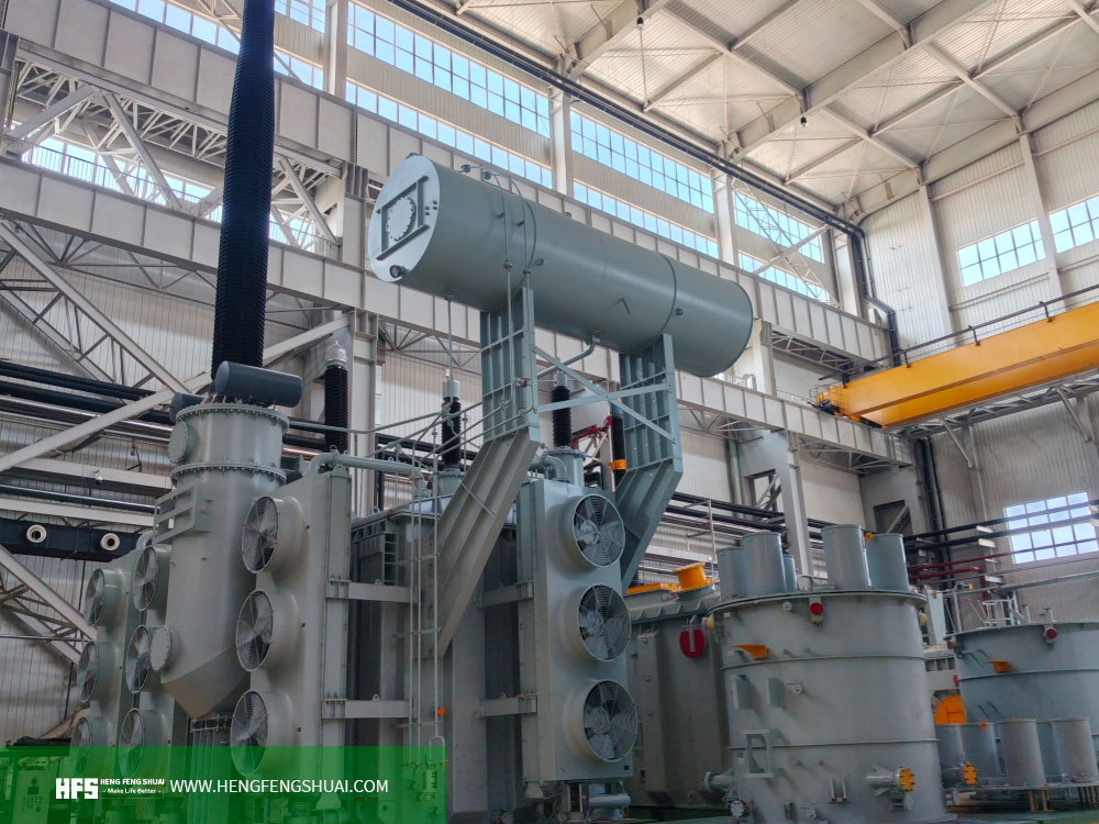
To meet the high‑voltage and large‑capacity power transmission requirements of the Albania 400 kV Hub Substation, Hengfengshuai Electric provides a customized technical solution for the 300 MVA‑400/220/33 kV three‑phase oil‑immersed autotransformer.
This solution targets power transmission and voltage regulation between the 400 kV and 220 kV high‑voltage power grids, with a 33 kV tertiary winding equipped. Combined with on‑load tap‑changing, short‑circuit withstand capability, on‑line Dissolved Gas Analysis (DGA) and multi‑layer mechanical protection design, it satisfies comprehensive demands of large‑scale hub substations for operational reliability, voltage stability and equipment condition monitoring.
400 kV‑class main transformers shall not only feature large‑capacity continuous operation capability, but also address engineering challenges including outdoor high‑pollution environment, insulation coordination, system short‑circuit shocks, seismic mechanical stress and long‑term operation & maintenance. In response to these requirements, this solution carries out systematic design covering electromagnetic performance, insulation system, cooling capacity, tap‑changing control, mechanical strength and on‑line diagnosis.
The equipment technical specifications are developed based on the IEC 60076 series of standards, and insulating oil complies with IEC 60296. Specific applicable standards, technical deviations, local grid connection conditions and project acceptance requirements shall be confirmed with the Owner, EPC Contractor and grid operator during the engineering design phase.
Core Solution Parameters
Rated Capacity: 300 MVA
Voltage Class: 400/220/33 kV
Equipment Type: Three‑phase oil‑immersed autotransformer
Cooling Mode: ONAN/ONAF
On‑load Tap‑changing Range: +10% to ‑10%
On‑line Monitoring: DGA on‑line monitoring for 9 key gases
Design Environment: Outdoor substation, high‑pollution and industrial environment
Seismic Design Requirement: 0.3 g continuous horizontal acceleration
Based on product technical specifications, this solution serves as a technical selection and equipment configuration reference for overseas power engineering projects for high‑voltage transmission hubs, regional grid interconnection and large‑scale substation construction.
Ⅱ. Typical Operating Conditions and Specialized Countermeasures for Albania 400 kV Hub Substation
1. Adaptation to 400 kV/220 kV Large‑Capacity Grid Interconnection
Operating Condition Description: A 400 kV hub substation is normally tasked with power exchange between high‑voltage transmission and regional power grids. The transformer shall operate continuously under rated load, while taking voltage regulation, insulation coordination and long‑term operational economy into account.
Specialized Design by Hengfengshuai Electric: a. Adopt 300 MVA rated capacity and 400/220/33 kV voltage configuration for interconnection between high‑voltage and medium‑voltage power grids. b. Adopt autotransformer structure; specific winding connection modes and system wiring shall be confirmed in accordance with the finally approved electrical schematic diagram and technical agreement. c. Equip a 33 kV tertiary winding to satisfy design requirements for the tertiary winding and its connected circuits. d. Adopt three‑phase five‑limb core structure and cold‑rolled grain‑oriented silicon steel (CRGO) with high magnetic permeability to balance electromagnetic performance and no‑load loss control.
2. Adaptation to High‑pollution Outdoor Environment and Insulation Reliability
Operating Condition Description: Outdoor high‑voltage equipment is continuously exposed to dust, industrial contaminants, humidity fluctuations and other external environmental factors. Contamination on bushing surfaces may reduce insulation margin, and degraded sealing performance may increase the risk of moisture ingress into the insulation system.
Specialized Design by Hengfengshuai Electric: a. Minimum creepage distance of high‑voltage bushings is designed for 31 mm/kV. Applicable voltage, pollution level and insulation coordination shall be confirmed in project engineering design. b. Configure lightning impulse and power‑frequency withstand voltage levels for high‑voltage, medium‑voltage, 33 kV tertiary winding and neutral point in compliance with technical specifications. c. Apply uninhibited Class I mineral transformer insulating oil conforming to IEC 60296. d. Equip bladder‑type oil conservator and silica‑gel dehydration breather to mitigate moisture ingress into the insulation system. e. Design and inspect the oil tank, sealing structures and bushing mounting positions in accordance with approved environmental and mechanical requirements.
3. Adaptation to Seismic Mechanical Stress and Equipment Structure
Operating Condition Description: Seismic events may impose mechanical stress on large transformer oil tanks, core clamping structures, winding supports, bushings and external connections. For large high‑voltage transformers, seismic resistance shall be verified through overall structural design and corresponding calculations or validation.
Specialized Design by Hengfengshuai Electric: a. Design for maximum continuous horizontal seismic acceleration of 0.3 g as per technical specifications. b. Perform mechanical design verification for core, windings, oil tank and key connecting structures. c. Confirm equipment interfaces considering on‑site foundation conditions, bushing layout, busbar connections and cable interfaces. d. Specific seismic acceptance criteria, calculation basis and applicable seismic spectra shall be defined in the project technical agreement.
4. Adaptation to Large‑capacity Operation and Temperature Rise Control
Operating Condition Description: A 300 MVA main transformer generates core loss and winding loss during long‑term loaded operation. Insufficient heat dissipation may lead to elevated oil and winding hot‑spot temperatures, accelerating insulation ageing and shortening equipment service life.
Specialized Design by Hengfengshuai Electric: a. Adopt ONAN/ONAF composite cooling system supporting natural cooling and forced‑air cooling operating modes. b. ONAN mode corresponds to 180 MVA capacity; ONAF mode corresponds to 300 MVA capacity. c. Oil temperature rise limit: 50 °C; winding temperature rise limit: 55 °C. Applicable ambient conditions and test methods shall be subject to the approved technical agreement. d. Equip independent Oil Temperature Indicator (OTI) and Winding Temperature Indicator (WTI) for operational temperature monitoring and alarm control. e. Verify thermal performance under specified loading conditions through cooling system design and temperature‑rise tests.
5. Adaptation to Grid Short‑circuit Faults and Electrodynamic Impacts
Operating Condition Description: Upon short‑circuit faults in high‑voltage transmission systems, transformer windings are subjected to significant electrodynamic and thermal stress. Winding deformation, insulation damage or structural loosening may endanger safe equipment operation.
Specialized Design by Hengfengshuai Electric: a. The transformer shall withstand mechanical stress from short‑circuit faults for a duration of 2.0 seconds as specified in technical specifications. b. Verify conditions associated with maximum 50 kA fault current on the 400 kV system. System fault level, fault location and actual current endured by the transformer shall be clarified in the engineering phase. c. High‑voltage winding impedance shall be designed for no less than 20 % as per specification requirements. d. Perform short‑circuit mechanical strength verification for winding supports, clamping structures, insulation gaps and key connection components. e. Final short‑circuit withstand capability shall be subject to system calculations, design validation and mutually‑approved technical documentation.
6. Adaptation to Voltage Fluctuation and Remote Tap‑changing Control
Operating Condition Description: Regional load variations and grid operation‑mode adjustments may cause voltage deviations. For 400 kV/220 kV grid‑interconnection equipment, on‑load tap‑changing enables ratio adjustment during operation to satisfy grid voltage control requirements.
Specialized Design by Hengfengshuai Electric: a. Equip high‑speed oil‑immersed transition‑resistor On‑Load Tap‑changer (OLTC). b. Tap‑changing range: +10 % to ‑10 %, with 17 operating positions and 1.25 % per step. Exact tap quantity, step size and end‑point definitions shall be reviewed during technical confirmation. c. The on‑load tap‑changing mechanism is arranged at the neutral‑end of the common winding; final configuration shall follow approved design drawings. d. Support remote SCADA control, local manual mechanical operation and linkage with Automatic Voltage Regulator (AVR). e. Define tap‑changing blocking, alarms, interlocks and remote status feedback interfaces in accordance with project control logic.
7. Adaptation to Long‑term Operation Fault Diagnosis and Equipment Protection
Operating Condition Description: Large power transformers constitute critical substation assets. Premonitory symptoms such as internal insulation anomalies, local overheating, changes in dissolved gas‑in‑oil or pressure anomalies may arise prior to obvious failures. Timely monitoring facilitates condition‑based maintenance planning.
Specialized Design by Hengfengshuai Electric: a. Install on‑line multi‑gas DGA monitoring device for continuous measurement of 9 gases: H₂, CH₄, C₂H₂, C₂H₄, C₂H₆, CO, CO₂, O₂ and N₂. b. Fit double‑float Buchholz relay with alarm and trip signal circuits. c. Install independent surge relay for the on‑load tap‑changer. d. Deploy oil temperature indicator, winding temperature indicator and dual independent spring‑loaded Pressure Relief Devices (PRD). e. Confirm configuration of alarm, trip, remote communication and condition‑monitoring signals per project control‑system interface requirements.
Ⅲ. Key Technical Parameters of Albania 300 MVA‑400/220/33 kV Three‑Phase Oil‑Immersed Autotransformer
|
Parameter Item |
Technical Specification |
Engineering Application Note |
|---|---|---|
|
Rated Capacity |
300 MVA |
For large‑capacity high‑voltage grid interconnection |
|
Rated Voltage |
400/220/33 kV |
Voltage configuration for high‑voltage, medium‑voltage and tertiary windings |
|
Equipment Type |
Three‑phase oil‑immersed autotransformer |
For high‑voltage power transmission and regional grid connection |
|
Vector Group |
YNa0d11 (original specification notation) |
Shall be reviewed against approved winding connection diagrams |
|
Cooling Mode |
ONAN/ONAF |
Natural oil‑circulation natural‑air cooling and forced‑air cooling |
|
ONAN Corresponding Capacity |
180 MVA |
60 % of rated capacity |
|
ONAF Corresponding Capacity |
300 MVA |
Full rated‑capacity operation |
|
Oil Temperature‑rise Limit |
50 °C |
Verified under approved test conditions |
|
Winding Temperature‑rise Limit |
55 °C |
Verified under approved test conditions |
|
Maximum No‑load Loss |
105 kW |
Reference temperature and measurement methods subject to technical agreement |
|
Maximum Load Loss |
320 kW |
Reference temperature 75 °C, per technical specification |
|
Maximum Auxiliary Cooling Power |
15 kW |
Cumulative power of fan motor assemblies |
|
Short‑circuit Withstand Duration |
2.0 s |
Subject to approved short‑circuit calculations and verification |
|
System Fault‑current Condition |
Max. 50 kA for 400 kV circuits |
System fault level and equipment endured conditions to be clarified |
|
High‑voltage Winding Impedance |
Min. 20 % |
Subject to final approved impedance definition and test reports |
|
High‑voltage Side Lightning Impulse Withstand Voltage |
1300 kVp |
Per original technical specification |
|
High‑voltage Side Power‑frequency Withstand Voltage |
570 kVrms, 1 min |
Per original technical specification |
|
220 kV Side Lightning Impulse Withstand Voltage |
950 kVp |
Per original technical specification |
|
220 kV Side Power‑frequency Withstand Voltage |
395 kVrms, 1 min |
Per original technical specification |
|
33 kV Tertiary Winding Lightning Impulse Withstand Voltage |
250 kVp |
Per original technical specification |
|
33 kV Tertiary Winding Power‑frequency Withstand Voltage |
95 kVrms, 1 min |
Per original technical specification |
|
On‑load Tap‑changing Range |
+10 % to ‑10 % |
Remote and local tap‑changing control |
|
On‑load Tap‑changing Positions |
17 positions, 1.25 % per step |
Tap configuration subject to engineering review |
|
Minimum High‑voltage Bushing Creepage Distance |
31 mm/kV |
Confirmed per project pollution level and insulation design |
|
Seismic Design Requirement |
0.3 g continuous horizontal acceleration |
Subject to project seismic calculation and acceptance criteria |
|
Core Structure |
Three‑phase five‑limb CRGO core |
Low‑loss, high‑magnetic‑permeability material |
|
Insulating Oil |
IEC 60296 Uninhibited Class I mineral insulating oil |
Subject to final procurement and acceptance documents |
|
On‑line Monitoring |
9‑gas DGA |
Enables transformer condition diagnosis |
|
Reference Design Standards |
IEC 60076 Series |
Final standard list subject to project contract |
Technical Note: The above parameters are extracted from product technical specifications for project solution preparation. Final procurement datasheets, equipment vector group, insulation coordination, short‑circuit withstand conditions, guaranteed loss values and test standards shall be agreed by both parties in the technical agreement and approved drawings.
Complete technical datasheets and English‑language documentation for project review can be obtained by contacting Hengfengshuai Electric.
Ⅳ. Core Value Advantages of the Albania 300 MVA‑400/220/33 kV Three‑Phase Oil‑Immersed Autotransformer Solution
1. 300 MVA Large‑capacity Autotransformer Construction for High‑voltage Grid Interconnection
To meet power‑transmission requirements between 400 kV and 220 kV voltage levels, this solution adopts a 300 MVA three‑phase oil‑immersed autotransformer equipped with a 33 kV tertiary winding.
400/220/33 kV voltage configuration for large‑scale transmission hubs
Autotransformer construction; final winding connections subject to detailed design
Three‑phase five‑limb CRGO core balancing magnetic performance and loss control
Electromagnetic design, insulation coordination and interface confirmation completed against project system parameters
2. Dual‑mode ONAN/ONAF Cooling Balancing Operational Economy and Capacity Demand
The equipment combines natural oil‑circulation natural‑air cooling and forced‑air cooling.
ONAN mode rated for 180 MVA
ONAF mode rated for full 300 MVA
Equipped with temperature‑measuring instruments for operational temperature supervision
Heat‑dissipation performance validated by thermal design and temperature‑rise tests
Actual sustainable loading capacity depends on ambient temperature, cooling‑system configuration, load profile and final temperature‑rise test results.
3. Low‑loss Design Optimizing Whole‑life‑cycle Cost of the Transformer
Large transformers continuously generate no‑load and load losses over long‑term operation. Proper loss control reduces energy consumption during grid operation.
Specification requirements for this solution:
Maximum no‑load loss: 105 kW
Maximum load loss: 320 kW at reference temperature 75 °C
Cumulative fan‑motor assembly power ≤ 15 kW
Low‑loss high‑permeability CRGO core material
During project procurement, guaranteed loss values may be included in technical evaluation. Economic comparison can be performed considering equipment service life, local electricity tariffs and capitalised loss coefficients.
4. Short‑circuit Withstand and Mechanical Protection Design Enhancing Safety Margin for Critical Equipment
400 kV hub equipment shall adequately address thermal and electrodynamic stress induced by system short‑circuit faults.
This solution performs design verification for the 2.0‑second short‑circuit withstand requirement, high‑voltage winding impedance requirement and winding mechanical supports. Buchholz relay, independent pressure‑relief devices and tap‑changer‑specific protections are fitted.
Specific protection settings, system fault current, fault current at equipment terminals and protection‑action logic shall align with grid‑calculation results.
5. OLTC On‑load Tap‑changing and SCADA Interfaces Enabling Voltage Control
The on‑load tap‑changer allows ratio adjustment during equipment operation responding to grid voltage‑control requirements.
Tap‑changing range: +10 % to ‑10 %
Local manual operation supported
Remote SCADA control supported
AVR automatic‑voltage‑regulation linkage supported
Tap‑changing status feedback, alarm and interlock interfaces configured per project requirements
Clear tap‑changing strategy and control‑interface definition facilitate integration with substation automation systems
6. On‑line DGA and Multi‑layer Protection Supporting Condition‑based Maintenance
The system is equipped with 9‑gas on‑line DGA monitoring complemented by temperature sensors, gas relay and pressure‑relay protections.
Continuous monitoring of key dissolved‑gas variations
Trend analysis for insulation and thermal faults
Protection signals via alarm and trip circuits
Data‑access methods and communication protocols confirmed per project requirements
On‑line monitoring provides auxiliary evidence for equipment condition assessment but shall not replace mandatory electrical tests, on‑site inspections and professional fault diagnosis.
Ⅴ. Custom Design and Factory Acceptance Test (FAT) for Albania 300 MVA‑400/220/33 kV Three‑Phase Oil‑Immersed Autotransformer
1. Project‑specific R&D Workflow
For the technical requirements of the Albania 400 kV Hub Substation, equipment design and manufacturing are recommended to follow the workflow below: a. Technical Specification Review: Confirm capacity, voltage class, frequency, vector group, insulation level, loss limits and cooling mode. b. Grid‑parameter Confirmation: Acquire system short‑circuit capacity, earthing scheme, operating‑voltage range, protection configuration and grid‑connection interface conditions. c. Electromagnetic and Thermal Design: Complete core, winding, impedance, loss and cooling‑system design. d. Insulation and Mechanical Design: Confirm bushing insulation coordination, creepage distance, winding supports, oil‑tank strength and seismic requirements. e. Control and Protection Design: Design interfaces for OLTC, SCADA, AVR, DGA, temperature instruments and protection circuits. f. Drawing and Technical‑agreement Approval: Commence production only after drawings are approved by the Owner or EPC Contractor.
2. Factory Acceptance Test (FAT)
Upon completion of manufacturing, Factory Acceptance Tests (FAT) shall be performed in accordance with contracted IEC standards, approved drawings and the technical agreement.
Recommended test scope: a. Winding DC resistance measurement b. Ratio, polarity and vector‑group verification c. No‑load loss and no‑load current measurement d. Load loss and short‑circuit impedance measurement e. Insulation resistance and specified dielectric‑performance tests f. Lightning‑impulse and power‑frequency withstand‑voltage tests per applicable standards and approved test protocols g. Full‑stroke operation, position‑indication and control‑circuit inspection for on‑load tap‑changer h. Functional check of temperature indicators, Buchholz relay, pressure‑relief devices and other protection equipment i. Temperature‑rise test, sealing test and other special tests as specified in the contract
FAT scope, test levels, witnessing arrangements and deliverable test reports shall be clarified prior to contract award. Customer or third‑party witnessing can be arranged upon project request.
Ⅵ. Overseas Project Delivery, Site Acceptance Test (SAT) and Operation‑Maintenance Support
1. International Shipment and Delivery Preparation
Cross‑border transportation of large power transformers requires careful attention to shipping dimensions, total weight, centre‑of‑gravity, lifting points, shock‑vibration, sealing protection and destination‑site transport conditions.
During delivery phase, confirm the following in accordance with the actual shipping scheme: a. Transport mode, packaging, anti‑moisture and anti‑corrosion requirements b. Transport securing, lifting and on‑site unloading schemes c. Protection of key components and receiving‑inspection requirements upon arrival d. Delivered technical documentation, drawings, test reports and spare‑parts list
Transport schemes for large main transformers shall be defined according to equipment dimensions, weight, transport route and manufacturer requirements; practices for small‑capacity distribution transformers shall not be directly applied.
2. Standardised On‑site SAT Installation and Acceptance
After equipment arrival on‑site, on‑site acceptance shall be jointly performed by the Owner, EPC Contractor, installation contractor and equipment supplier under respective project responsibilities. a. Inspect oil tank, bushings, radiators, accessories and transport‑condition status. b. Complete positioning and connection in compliance with approved foundation drawings, earthing schemes and installation specifications. c. Verify equipment nameplate data, wiring, tap position and accessory configuration. d. Perform on‑site insulation, ratio, winding‑resistance and protection‑function checks in accordance with approved on‑site test protocols. e. Verify OLTC, temperature monitoring, DGA and substation‑control‑system interfaces. f. Document on‑site acceptance and complete pre‑commissioning checks following grid‑connection procedures.
Exact SAT test scope and commissioning procedures shall comply with local grid codes, contract provisions and approved on‑site commissioning plans.
3. After‑sales Operation‑Maintenance and Technical Support
For long‑term reliable transformer operation, establish equipment records and periodic maintenance regimes. a. Deliver contracted technical documentation, connection diagrams, test reports and operation‑maintenance manuals. b. Provide remote technical support and installation‑commissioning guidance upon project request. c. Maintain records for oil‑chromatography, oil temperature, winding temperature, load and protection‑trip events. d. Periodically inspect bushings, sealing elements, cooling systems, tap‑changer mechanisms and protection devices following manufacturer maintenance instructions. e. Supply spare parts and follow‑up technical services as stipulated in the commercial contract.
Warranty duration, service response time, on‑site service arrangements and spare‑parts supply conditions are subject to the signed commercial contract between both parties.
Ⅶ. Frequently Asked Questions for Albania 400 kV Hub Substation Project
Q1: What application scenarios are suitable for the 300 MVA‑400/220/33 kV autotransformer? A: This specification is intended for 400 kV‑to‑220 kV high‑voltage grid interconnection and large hub‑substation applications. The 33 kV tertiary winding fulfils relevant system‑design requirements. Actual suitability shall be verified against grid topology, load requirements, short‑circuit capacity and protection schemes.
Q2: Does this 400 kV power transformer support on‑load tap‑changing during operation? A: The technical specification includes an On‑Load Tap‑changer (OLTC) with tap‑changing range from +10 % to ‑10 %, supporting local manual operation, remote SCADA control and AVR linkage. Exact tap configuration, control logic and communication interfaces shall be confirmed in the project technical agreement.
Q3: How does the equipment monitor internal insulation and potential faults? A: The solution integrates an on‑line multi‑gas DGA monitoring device continuously measuring 9 key gases. It is complemented by Buchholz relay, temperature indicators and pressure‑relief devices to support operational‑condition analysis, abnormal‑event alarming and protection‑trip actuation.
Q4: What are the no‑load loss and load‑loss values of the transformer? A: Current technical specifications specify maximum no‑load loss of 105 kW and maximum load loss of 320 kW (at reference temperature 75 °C). For formal procurement, guaranteed loss values, measurement methods and factory test reports shall prevail.
Q5: Does the equipment satisfy grid‑connection requirements of the Albanian power system? A: This documentation adopts IEC 60076‑series standards as one of the design bases, but does not constitute proof of specific local‑grid certification or project approval. Prior to tendering and procurement, verify the latest technical specifications, grid‑access requirements, test documentation and approval workflows issued by the Albanian grid operator.
Q6: How can I obtain complete technical datasheets and project quotations? A: Please provide project single‑line diagram, rated capacity, voltage levels, system short‑circuit parameters, tap‑changing requirements, environmental conditions, applicable standards, delivery location and expected delivery schedule. Hengfengshuai Electric will validate technical requirements and prepare technical documentation and commercial quotations based on finalised technical scope.
Ⅷ. Summary and Consultation for Albania 400 kV Hub Substation Solution
The 300 MVA‑400/220/33 kV three‑phase oil‑immersed autotransformer is designed for high‑voltage transmission hubs and regional grid interconnection. It integrates large‑capacity operation, ONAN/ONAF cooling, on‑load tap‑changing, short‑circuit‑withstand design, on‑line DGA monitoring and multi‑layer mechanical protection to deliver a comprehensive technical solution covering electrical performance, operational control and equipment condition diagnosis.
For high‑voltage power‑construction projects in Albania and other European markets, transformer selection shall not only focus on rated capacity and voltage class, but also systematically evaluate loss figures, insulation levels, short‑circuit conditions, environmental adaptability, seismic requirements, control interfaces and on‑site acceptance codes.
Hengfengshuai Electric can support project‑specific technical specification review, product selection, parameter cross‑checking, drawing approval, factory‑test coordination and delivery‑solution communication. Actual equipment configuration, applicable standards, delivery lead‑time, certification documents and service scope shall be governed by the project technical agreement and commercial contract.
Project Technical Consultation & Inquiry
E‑mail: hfs@hengfengshuai.com
To obtain technical documentation or commercial quotations for the 300 MVA‑400/220/33 kV autotransformer, please contact Hengfengshuai Electric and provide project technical specifications, single‑line diagrams and expected delivery schedule for further technical‑solution confirmation.

Qingdao Hengfengshuai Electric Co., Ltd
WhatsApp: +86 152 6625 8801
Address: No. 251, Xingyang Road, Chengyang District, Qingdao, Shandong
Email: hfs@hengfengshuai.com
Customer service email: service@hengfengshuai.com
website:https://www.hengfengshuai.com