1 Project Overview and Technical Specifications
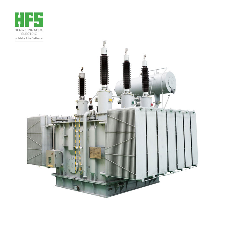
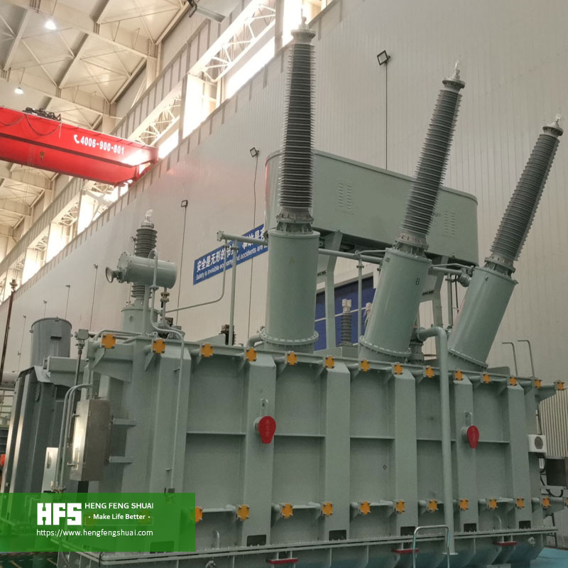
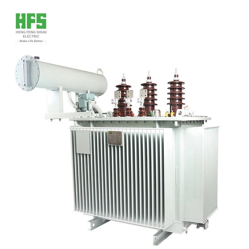
This solution is provided by Hengfengshuai Electric for the delivery of 2 units of 40MVA-110kV three-phase oil-immersed power transformers for the digital substation project in Balkhash District, Almaty Oblast of Kazakhstan National Grid. With a rated capacity of 40MVA and a voltage class of 110kV, the transformer is the core main equipment of the substation. In accordance with user requirements, the transformer adopts an on-load tap-changer (OLTC) mode and a connection group of YNd11, meeting the voltage stability requirements of industrial parks or regional power grids. The complete cycle from design confirmation to on-site delivery is 55 days.
Table: Main Technical Parameters of the Transformer
Parameter NameTechnical IndicatorRemarksModelSZ20-40000/110Three-phase, OLTC, oil-immersed self-cooled
Rated Capacity40MVAContinuous rated capacity
Voltage Combination110±8×1.25%/10.5kVOLTC on the high-voltage side
Connection GroupYNd11Commonly used for step-down transformers
Short-circuit ImpedanceUk=10.5%Standard impedance value
Cooling MethodONAN/ONAFOil Natural Air Natural / Oil Natural Air Forced
2 Design and Development Phase
2.1 Electromagnetic Scheme Design
First, the design team conducts electromagnetic calculations based on the technical agreement to determine core parameters such as core diameter, winding turns, and conductor specifications. Professional simulation software is used for accurate calculation of short-circuit impedance, losses and temperature rise to ensure that the performance indicators meet the requirements of GOST-R standards. For the 40MVA capacity, the iron core usually adopts high magnetic permeability grain-oriented silicon steel sheet (27ZH100) to reduce no-load loss and no-load current.
2.2 Structural Drawing Design
After the completion of the electromagnetic scheme, the design of a full set of construction drawings is carried out (a 3-person technical team takes about 18 days), including:
Iron core drawings: determining the iron core grade, lamination method (six-step step-lap lamination) and clamping structure
Winding drawings: determining the coil winding method, turn insulation thickness and oil channel distribution
Insulator drawings: designing insulation structures such as angle rings, electrostatic plates and end rings
Oil tank drawings: conducting finite element analysis (ANSYS) on the strength of the oil tank to avoid leakage caused by stress concentration
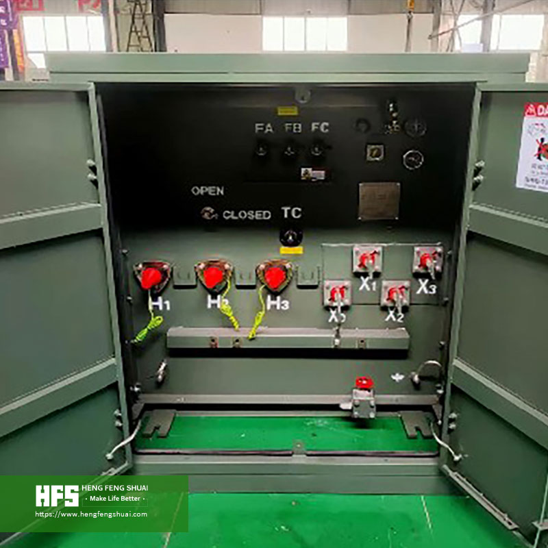
Component selection: selecting Shanghai Huaming CV III 350Y/110-10193W tap-changer, and matching accessories such as bushings (Xigao) and gas relays
2.3 Design Review
After the completion of the design, an internal review is organized to examine the electromagnetic scheme, structural strength and process feasibility, ensuring that the design scheme meets the technical agreement and has manufacturability.
3 Production and Manufacturing Phase
3.1 Material Procurement and Inspection
Raw materials are procured in accordance with the design drawings, and key materials include:
Silicon steel sheet: high magnetic permeability grain-oriented silicon steel, with magnetic performance retested
Copper conductor: flat copper wire drawn from T1 oxygen-free copper rod, with resistivity and tensile strength tested
Insulating materials: insulating cardboard, cable paper, laminated wood, etc., with water content and electrical strength tested
Transformer oil: naphthenic base oil complying with GB 2536 standard (KunLun 40#, resistant to low temperature of minus 40 degrees Celsius)
All materials must be inspected by the Supplier Quality Assurance (SQA) of Hengfengshuai Electric before warehousing, and non-conforming products are not allowed to be put into production.
3.2 Iron Core Manufacturing
Silicon steel sheets are processed into the required shapes through slitting and shearing lines, deburred and then coated with an insulating layer. The iron core lamination adopts the six-step step-lap lamination process to reduce the magnetic resistance and no-load loss at the joints. After the completion of lamination, an iron core test is carried out to measure the no-load loss and no-load current, and compare them with the design values. After passing the test, the upper and lower clamps are installed, and the clamping force is strictly controlled.
3.3 Coil Manufacturing
The coil is the core component of the transformer, and the manufacturing process requires a clean environment and controlled temperature and humidity. The winding process strictly controls the accuracy of turns, correct transposition and tight and even winding. For the 40MVA/110kV transformer, the high-voltage coil usually adopts a continuous structure, and the low-voltage coil adopts a helical or foil winding structure. After the winding of each coil is completed, DC resistance measurement and turn check are carried out to ensure electrical performance.
3.4 Insulator Processing
Insulators are cut and formed by CNC machining centers to ensure dimensional accuracy. Key insulators such as angle rings and electrostatic plates are manually wrapped, and the creepage path is strictly controlled. The processed insulators are dried to remove moisture and prevent partial discharge.
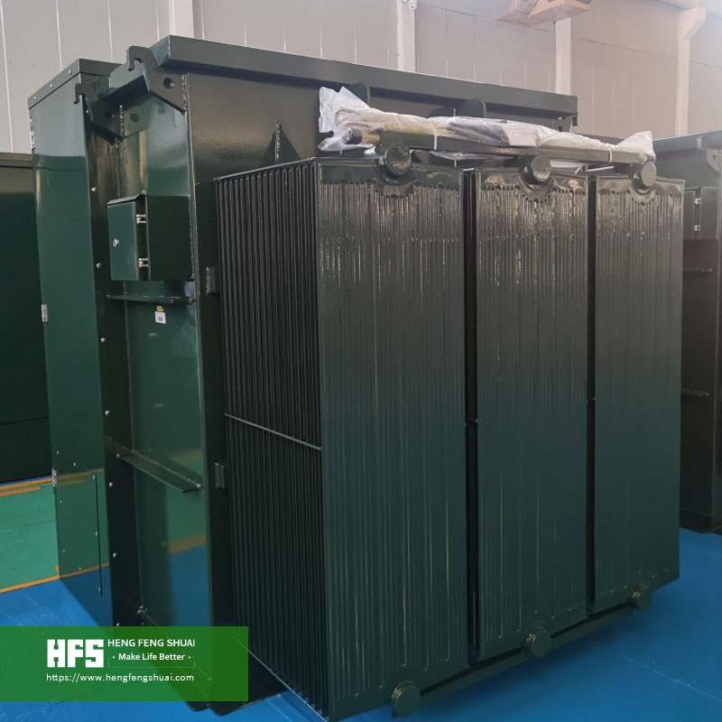
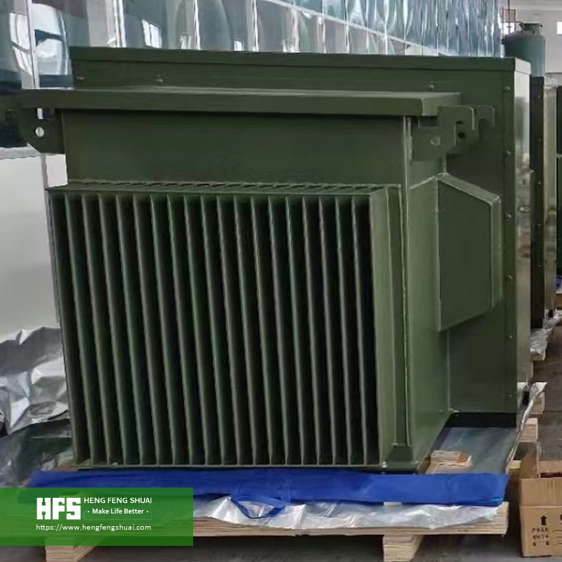
3.5 Oil Tank Manufacturing
Steel plates are cut and welded into shape, and a kerosene leakage test is carried out to check the weld quality. After welding, the oil tank is sandblasted to remove oxide skin and rust, and then coated with primer, intermediate paint and topcoat. After spraying, a mechanical strength test is carried out, applying positive and negative pressure to check the deformation of the oil tank and the reliability of the welds. The customer requires C4 grade corrosion resistance for the shell.
3.6 Core Assembly
The wound coils are sleeved on the iron core columns, insulators are installed, leads are connected, and tap-changers are mounted. The cleanliness is strictly controlled during the assembly process to prevent residual metal foreign bodies and dust. Lead welding adopts silver-copper welding to ensure mechanical strength and electrical conductivity.
3.7 Drying Treatment
The transformer core requires three times of drying treatment (total drying time of 72 hours):
First drying: pre-drying after the completion of coil winding
Second drying: drying after the sleeving of high and low voltage coils
Third drying: vacuum drying of the fully assembled core in a drying tank
Drying adopts kerosene vapor phase drying or vacuum hot air drying to remove moisture from insulating materials and ensure insulation performance.
3.8 Final Assembly
The dried core is hoisted into the oil tank, and accessories such as oil tank cover, bushings, conservator and radiators are installed. Leads are connected in accordance with the drawings, and monitoring components such as temperature measuring devices and gas relays are installed. After final assembly, vacuum treatment is carried out with a vacuum degree ≤133Pa maintained for more than 24 hours, and then vacuum oil filling is performed.
4 Test and Verification Phase - Factory Acceptance Test (FAT)
4.1 Routine Tests
Hengfengshuai Electric must conduct a full set of routine tests for each transformer before delivery, including:
Winding DC resistance measurement: measured at all tap positions, with the three-phase unbalance rate complying with the standard
Voltage ratio measurement and connection group label verification: verifying the transformation ratio and polarity at all tap positions
Insulation resistance, absorption ratio or polarization index measurement: evaluating the moisture condition of insulation
Dielectric loss factor (tanδ) and capacitance measurement: detecting the overall condition of insulation
AC withstand voltage test of windings with bushings: short-time power frequency withstand voltage test for main insulation
Transformer oil test: breakdown voltage, micro water and chromatographic analysis
No-load loss and no-load current measurement: measured at rated voltage
Load loss and short-circuit impedance measurement: measured at the rated tap
4.2 Type Tests
For the first product, type tests are also required to verify the design:
Temperature rise test: simulating operation under rated load to verify the temperature rise of windings and top oil
Lightning impulse test: full-wave and chopped-wave impulse to test the insulation's ability to withstand lightning overvoltage
Partial discharge measurement: discharge quantity ≤100pC at 1.5Um/√3 voltage
Sound level measurement: measuring the noise level to ensure ≤65dB(A)
4.3 Special Tests
Special tests are conducted according to user requirements:
Winding deformation test: measured by frequency response method, with the original waveform retained as a reference for comparison after commissioning
Short-circuit withstand capacity test: verifying the transformer's ability to withstand short-circuit current
Zero-sequence impedance measurement: used for system protection setting
All test records are sorted and filed to form a factory test report (FAT), which is delivered to the user together with the product.
5 Packaging and Transportation Phase
5.1 Dismantling and Protection
After passing the test, some accessories need to be dismantled for easy transportation:
Dismantle accessories such as bushings, conservators and radiators and package them separately
Install cover plates for sealing on all flange interfaces and fill with dry nitrogen for protection (pressure 0.01-0.03MPa)
Retain the residual transformer oil in the core to keep the insulation impregnated
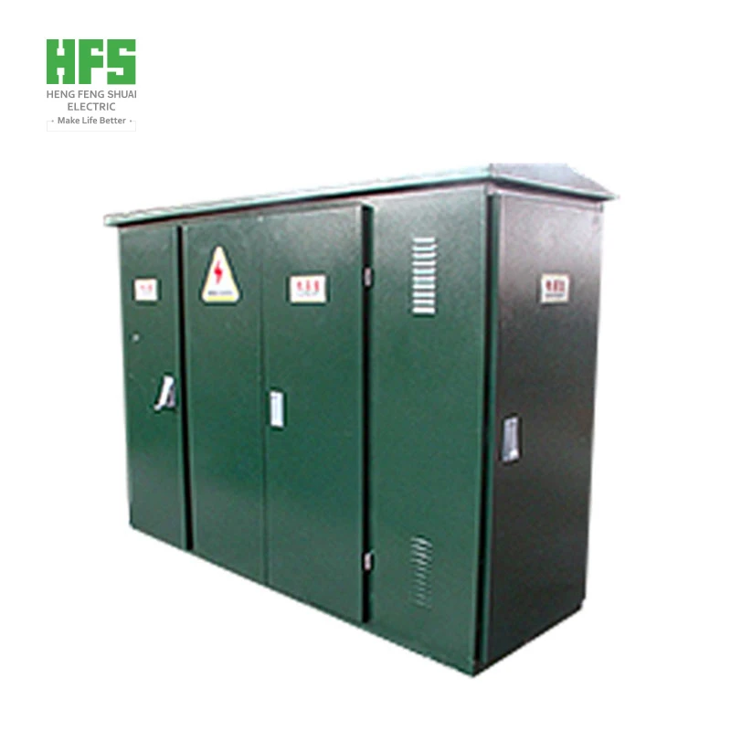
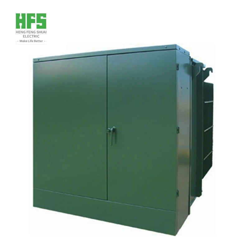
5.2 Packaging
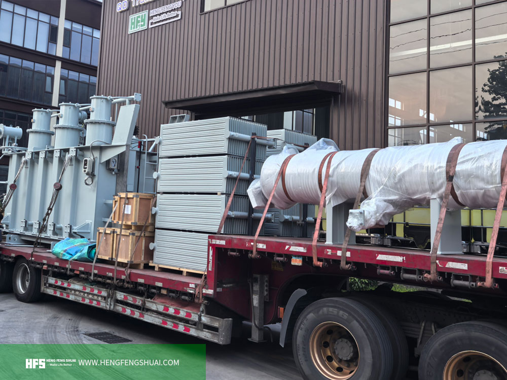
The oil tank body is packaged with a wooden bracket + waterproof cloth, and accessories are transported in wooden cases. Markings such as center of gravity position, lifting points and no inversion are marked on the outside of the packing cases. Documents included with the cases are: factory certificate of conformity, test report, installation and operation instructions, and packing list.
5.3 Transportation
The net weight of the 40MVA/110kV transformer body is about 38.7 tons (excluding oil), and it is transported by road with a multi-axle semi-trailer. Before transportation, apply for a heavy cargo transportation permit, plan the transportation route, and remove obstacles such as height and weight limits of bridges and culverts. Four 3D shock recorders are installed during transportation to monitor vibration and shock during transportation.
6 On-site Delivery and Installation
6.1 On-site Handover
After the goods arrive at the site, the user and the supplier conduct joint unpacking and acceptance:
Check for damage, rust and oil leakage on the appearance
Verify whether the quantity of accessories is consistent with the packing list
Check whether the nitrogen pressure is normal to judge whether there is leakage during transportation
Read the shock recorder data to confirm that the shock during transportation does not exceed the standard
6.2 On-site Installation
Key processes for on-site installation of the transformer:
Positioning: unload and position the transformer body with a crane or hydraulic jack
Accessory installation: install accessories such as radiators, bushings, conservators and oil pipes
Vacuum oil filling: pump to the specified vacuum degree and then fill with qualified transformer oil
Standing and air exhaust: stand for 48 hours after oil filling and discharge gas in the gas relay for many times
6.3 On-site Handover Test
After the completion of installation, the handover test is carried out in accordance with the national standard DL/T 5161.3-2018:
Transformer oil test (simplified analysis and chromatographic analysis)
DC resistance measurement of windings with bushings
Recheck of voltage ratio and connection group label
Measurement of insulation resistance, absorption ratio and polarization index
Dielectric loss factor measurement
Winding deformation test: compare with the factory waveform to judge whether there is damage during transportation and installation
AC withstand voltage test or induced withstand voltage test with partial discharge measurement
OLTC action test
Inspection and switching test of the cooling system
Calibration of gas protection
6.4 Power-on Commissioning
After passing the test, clean the site and restore all protection connections. Conduct five no-load inrush closing tests to check the impact of inrush current on protection and any abnormal noise. After 24 hours of no-load operation without abnormality, the transformer is officially put into load operation.
7 Whole-process Quality Control
7.1 Key Control Points
Design review: production can only be carried out after the scheme is approved
Material inspection: 100% retest of main materials
Process inspection: iron core test, semi-finished product inspection and core cleanliness inspection
Factory test: delivery is only allowed after passing all items of the factory acceptance test
Transportation monitoring: full-process monitoring by four shock recorders
On-site handover: comparative analysis of test data after installation and factory test data
7.2 Document Delivery
A complete set of technical documents is finally delivered to the user:
Transformer factory certificate of conformity
FAT factory test report
Installation, operation and maintenance instructions
Accessory instructions (tap-changer, bushing, gas relay, etc.)
Assembly drawings (electronic version)
SAT Site Acceptance Test report
8 Summary
The solution provided by Hengfengshuai Electric for the digital substation project in Balkhash District, Almaty Oblast of Kazakhstan National Grid is not just a simple delivery of equipment, but an in-depth optimization of the adaptability of "Made in China" in the global power transmission and distribution market. Contact Hengfengshuai Electric immediately (hfs@hengfengshuai.com) to obtain localized and customized power solutions complying with international standards for your substation project.